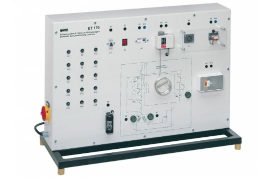
GUNT Identifying electrical faults in air conditioning systems requires comprehensive knowledge including the design and operation of electrical components and reading circuit diagrams. The GUNT ET 170 helps acquire this knowledge.
Product Features
- Demonstrates the electrical circuit of a simple air conditioning system
- Includes refrigerant compressor and fan at the air cooler (motors simulated)
- Compressor controlled via thermostat
- Fan motor speed switchable in two stages via ballast
- Compressor motor start via start-up relay and start-up capacitor
- Typical protection devices such as circuit breaker integrated
- Operating states of compressor and fan motors indicated by lamps on the front panel circuit diagram
- Simulation of 15 different faults including coil fracture and faulty switching contact
- Fault diagnosis using voltages and resistances at lab jacks with multimeter
- Front panel circuit diagram aids in locating measurement points
Benefits
- Hands-on experience with electrical fault diagnosis in air conditioning systems
- Clear visualization and simulation of faults for training
- Improves understanding of electrical circuits and protection devices
Why Choose the GUNT Electrical Faults In Simple Air Conditioning Systems?
This trainer offers practical fault simulation and diagnosis in a controlled environment, ideal for education in HVAC electrical systems.