GUNT Electrical faults in refrigeration systems requires comprehensive knowledge of component design, operation, and circuit diagram interpretation. The GUNT ET 172 trainer helps acquire this essential knowledge.
Product Features
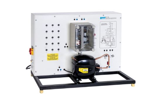
- Transparent showcase with clearly arranged and pre-wired electrical components
- Includes capacitor and start-up relay for motor examination
- Typical protection devices such as circuit breaker and automatic fuse are visible
- Simulation of 15 different electrical faults, including coil fractures, short circuits, and welded contacts
- Fault diagnosis using voltage and resistance measurements at lab jacks with a multimeter
- Front panel circuit diagram for easy identification of measuring points
Benefits
- Hands-on fault diagnosis training with realistic component faults
- Develop skills in electrical troubleshooting of refrigerant compressors
- Improves understanding of protection devices and fault detection
Why Choose the GUNT Electrical Faults In Refrigerant Compressors?
This trainer provides practical training to identify and diagnose electrical faults in refrigerant compressor circuits, enhancing troubleshooting skills and system reliability.