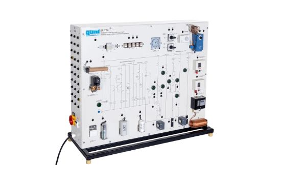
The GUNT Electrical Faults Trainer for Full Air Conditioning Systems provides comprehensive training on identifying and diagnosing electrical faults in complex HVAC systems. This advanced trainer includes the actual control circuits and simulated load components such as compressor, heater, and four-way reversing valve, replicating real-world operation with heat pump functionality.
Designed to teach essential skills in electrical fault analysis, this model allows users to explore 30 different fault scenarios, including coil fractures and faulty relays. The clear front-panel circuit diagram with indicator lamps assists in visualizing the operating state and locating measurement points for voltages and resistances.
Product Features
- Simulates electrical circuits of full air conditioning systems with heat pump operation
- Includes actual control circuits and simulated load components
- Hot gas defrosting and electrical auxiliary heating functions integrated
- Hygrostat-controlled humidifying for low humidity conditions
- Typical protection devices such as circuit breaker and frost protection monitor
- Front panel circuit diagram with lamps for operational feedback
- Simulates 30 different electrical faults for hands-on fault diagnosis
- Measurement points accessible for multimeter testing of voltages and resistances
Benefits
- Hands-on training in electrical fault identification in HVAC systems
- Realistic simulation improves practical understanding of fault diagnosis
- Facilitates learning of electrical circuit diagrams and measurement techniques
- Supports education in both heating and cooling system electrical components
Why Choose the GUNT Electrical Faults Trainer?
The GUNT Electrical Faults Trainer is an indispensable educational tool for HVAC technicians and engineering students. It delivers realistic fault simulation and comprehensive training on full air conditioning systems with heat pump functions, helping users develop expert diagnostic skills for maintenance and troubleshooting in professional environments.